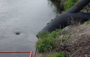
Vortices are a category of swirling flow involving the relationship between the suction nozzle of the pump and the entry configuration of the liquid as it enters. Swirling flow can be very detrimental to pump performance. Here are some of the effects:
- Free-surface vortices which if strong enough, draw air from the free surface into the pump, causing unbalanced loading of its impeller, periodic vibration, and reduction in pump capacity;
- Subsurface vortices, which originate from the floor, backwall, or sidewalls, and in the case of a pressurized sump from a ceiling, entering the pump and causing vibration and cavitation;
- Prerotation of the flow entering the pump which alters the angle of attack of the impeller blades, thereby, potentially affecting pump efficiency and causing cavitation;
- An uneven distribution of flow at the pump throat which results in unbalanced
loading of the pump impeller; - Significant unsteadiness of flow at the pump throat which causes vibration and
cavitation; and, - Flow separation at the pump-suction bell, which causes nonuniform flow at the
impeller and possible cavitation.
A vortex occurs when the pressure of the liquid becomes insufficient to prevent the organizing of the liquid molecules as they become aligned and begin to rotate on an axis line. We are all familiar with the action that happens when a sink or bathtub empties to drain. As the weight (pressure) of the water diminishes a vortex forms.
Fortunately, research has been done on this issue which has resulted in the Submergence Law. Sounds a little “highfalutin” for a simple vortex, but if you are experiencing these pump busters, you might think otherwise.
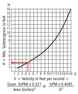
The determining factors of vortex creation are fluid velocity (V), flow (Q) and inlet diameter (D). Fluid velocity is calculated by the following formula: Q X 0.4085/D2

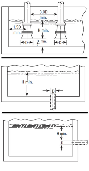
Eminent pump expert, Larry Bachus, has published a formula using calculated velocity and the chart on the left. Drawing a line vertically up from the calculated velocity, one can observe the recommended submergence at the corresponding intersection on the y axis of the chart. For example: If our pump has a 6″ inlet and is pumping 400 gpm we can calculate velocity using the formula which gives us this result: 400 X 0.4085/6 X 6 = 4.54. Drawing a line up from 4.5 on the chart to the curved line and then across reveals a Minimum Submergence (H) of slightly over 2 feet. Taking a look at the images below, we can see the necessary relationships between fluid level and infrastructure in order to avoid swirling flow and vortexing.

The Hydraulic Institute uses a slightly different method. Their formula does not require a chart and uses the formula: H = D + 0.574Q/D1.5
- Where H is submergence in inches
- D is bell diameter in inches
- Q is rate of flow in gpm
If we use the previous example of 400 gpm and 6″ of pipe then the formula would be solved: 6 + (0.574 X 400) / 14.69 = 21.6. As you can see, this answer is more precise than using the chart, but the result is approximately the same. However, calculating D to the 1.5 power might be difficult unless you have a scientific calculator so I made an Excel spreadsheet that you can download by clicking on this link: Submergence Law Formula
Often vortex breakers and special designs are incorporated into tanks and sumps to prevent vortices and swirling flow. Swirling flow and turbulent flow are issues affecting pump performance, subjects which I will cover in more detail in subsequent posts. I welcome your responses to this post below.
Links:
- Piping by Larry Bachus | Know and Understand Centrifugal Pumps by Larry Bachus
- Hydraulic Institute Page on Submergence
- Hydraulic Institute ANSI Standards: Intake Design for Rotodynamic Pumps (ANSI/HI 9.8)
- Pump Fundamentals: Calculating Minimum Submersion
- Subsurface Vortex Suppression in Water Intakes with Multiple-Pump Sumps